
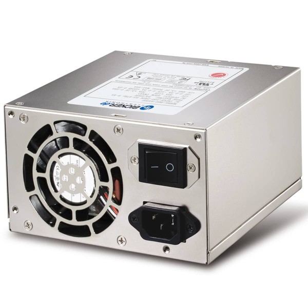
BEA-640 Industrial PC power supply / 400W / 90-264V / PFC / ATX12V / AC-DC / PS2 / 24-7 / 62368-1
From -10…+50 °C 400 Watt continuous power without restriction
- Noise immunity for industrial sectors
- High-quality electrolyte capacitors (+105 °C)
- Designed for continuous operation 24/7
Article is immediately available
| Quantity | Unit price |
|---|---|
| 1 to 9 | €347.12 * |
| From 10 | €258.23 * |
| From 50 | €245.85 * |
*Prices incl. 19% VAT plus shipping costs
Weight: 2.1 kg
The 400 W PC power supply BEA-640 is distinguished by very high reliability and long service... more
*** NRND – not recommended for new designs ***
"BEA-640"
The 400 W PC power supply BEA-640 is distinguished by very high reliability and long service life. By its integrated 4 kV surge input filter the BEA-640 is also suitable for highly demanding industrial applications. Within an ambient temperature range of -10 up to +50 °C full power can be supplied continuously without restrictions. The temperature regulated ball-bearing fan provides a tacho signal and can continuously be monitored by the board, which is very important with regard to system reliability.
| Output voltage: | ATX |
| Input voltage: | AC |
| Output power in W: | 400 |
| Mounting: | ATX |
WEEE-Nr: DE18400369
"BEA-640"
X1-132 

Power cord IEC-60320-C13 connector
- Power cord / IEC-320-C13
- 3G 0,75mm², Length: 1800 mm
1-9 pieces €7.62 incl. VAT.
Article is immediately available
Data sheet
Operation manual
3D Step
IUPS-401-B1 

400VA / 230VAC / 50/60Hz
- Integrated, space-saving UPS solution
- Serial (open collector) interface
- Reboot function
- Wall bracket available
1-9 pieces €235.50 incl. VAT.
Article is immediately available
BEA-630H 

300W / ATX12V
- Designed for 24/7 operation
- Additional -5VDC output
- Efficiency up to 87%
1-9 pieces €142.56 incl. VAT.
Article is immediately available
BEA-630 

300W / ATX12V
- Noise immunity for industrial sectors
- High-quality electrolyte capacitors
- Designed for continuous operation 24/7
1-9 pieces €303.21 incl. VAT.
Article is immediately available
BEA-560H 

600W / ATX12V
- Efficiency up to 86%
- Increased interference resistance
- Designed for continuous operation 24/7
1-9 pieces €320.70 incl. VAT.
Article is immediately available
BEA-540H 

400W / ATX12V
- Efficiency up to 85 %
- Increased interference resistance
- Designed for continuous operation 24/7
1-9 pieces €262.40 incl. VAT.
Article is immediately available
BEA-630 
300W / ATX12V
- Noise immunity for industrial sectors
- High-quality electrolyte capacitors
- Designed for continuous operation 24/7
1-9 pieces €303.21 incl. VAT.
Article is immediately available
BEA-550K 

500W / ATX12V
- High efficiency up to 92%
- Designed for continuous operation 24/7
- No minimum load required!
- 3 years warranty
1-9 pieces €183.26 incl. VAT.
Article is immediately available
BEA-635 

350W / ATX12V
- Noise immunity for industrial sectors
- High-quality electrolyte capacitors
- Operating temperature -10...+70°C
1-9 pieces €324.28 incl. VAT.
Article is immediately available
BEA-646 

460W / ATX12V
- High-quality electrolyte capacitors
- Ball-bearing fan with tacho signal
- Designed for continuous operation 24/7
1-9 pieces €433.04 incl. VAT.
Article is immediately available
BEA-630H 
300W / ATX12V
- Designed for 24/7 operation
- Additional -5VDC output
- Efficiency up to 87%
1-9 pieces €142.56 incl. VAT.
Article is immediately available
BEA-560H 
600W / ATX12V
- Efficiency up to 86%
- Increased interference resistance
- Designed for continuous operation 24/7
1-9 pieces €320.70 incl. VAT.
Article is immediately available
BEA-550H 

500W / ATX12V
- Efficiency up to 85 %
- Increased interference resistance
- Designed for continuous operation 24/7
1-9 pieces €295.24 incl. VAT.
Article is immediately available
BEA-750H 

500W / ATX12V additional +24V output
- Additional +24V/7A output
- Efficiency up to 91%
- Designed for continuous operation 24/7
- 3 years warranty
1-9 pieces €263.35 incl. VAT.
Article is immediately available
BEH-531H 

300W / Flex ATX
- High efficiency up to 91%
- No minimum load required
- Wide temperature range -10…+60°C
- 3 years warranty
1-9 pieces €113.88 incl. VAT.
Article is immediately available
BES-540C 

400W / 24VDC Input
- DC PC power supply
- TÜV and UL approved
- High efficiency >81%
- 3 years warranty
1-9 pieces €406.38 incl. VAT.
Item can be pre-ordered
BEA-586H 

860W / ATX12V
- Efficiency up to 86%
- Excellent regulation
- Designed for continuous operation 24/7
1-9 pieces €490.04 incl. VAT.
Article is immediately available
ENSP3-450P-USB 

350W / UPS function / USB
- UPS power supply for industrial PC
- Temperature range 0...+60°C
- Designed for 24/7 operation
- USB Interface
1-9 pieces €469.22 incl. VAT.
Article is immediately available
BEA-576H 

760W / ATX12V
- Efficiency up to 86%
- Excellent regulation
- Designed for continuous operation 24/7
1-9 pieces €438.28 incl. VAT.
Article is immediately available
HNSP9-520P-USB 

400W / UPS function / USB
- UPS PC power supply for industry
- Operating temperature range 0°...60°C
- USB interface
1-9 pieces €474.81 incl. VAT.
Item can be pre-ordered
DC300WS 

300W / 6-36VDC Input
- Fanless design for conduction cooling
- Selectable output +12V, +19V or +24VDC
- Very high efficiency up to 98%
- 3 years warranty
1-9 pieces €178.02 incl. VAT.
Article is immediately available
BES-540T 

400W / -36...-72VDC Input
- DC PC power supply
- TÜV and UL approved
- High efficiency >80%
- 3 years warranty
1-9 pieces €488.73 incl. VAT.
Item can be pre-ordered
IUPS-401-B1 
400VA / 230VAC / 50/60Hz
- Integrated, space-saving UPS solution
- Serial (open collector) interface
- Reboot function
- Wall bracket available
1-9 pieces €235.50 incl. VAT.
Article is immediately available
BEP-520C 

200W / 24VDC Input
- 24VDC ATX converter
- Fanless design for conduction cooling
- Galvanic isolation input/output
- Design-Lifetime 12+ years
1-9 pieces €295.12 incl. VAT.
Article is immediately available
X1-116 

ATX20/AT Adapter
- Supply of AT mainboards
- Length 100 mm
1-9 pieces €19.40 incl. VAT.
Article is immediately available
UPSI-2406DP2 

96W / 24VDC 4A
- DC UPS with Supercaps inside
- Operating temperature range -20...+65°C
- Power-fail Timer
- Approved to IEC/EN/UL 61010-1
1-9 pieces €284.41 incl. VAT.
Article is immediately available
MPSM-5600V 

600W / ATX / Medical
- Ideal for medical image processing
- Complies to IEC/EN60601-1 3.1 Ed
- No minimum load required
1-9 pieces €435.78 incl. VAT.
Article is immediately available
UPSIC-2403 

72W / 24VDC 3A
- Compact 24V DC-UPS
- Supercaps - maintenance-free
- Software UPS Control Center
- Extended temperature range
1-9 pieces €192.30 incl. VAT.
Article is immediately available
UPSI-2406DP1 

96W / 24VDC 4A
- DC UPS with Li-Ion battery inside
- Minimum load detection
- Power-fail Timer
- Approved to IEC/EN/UL 61010-1
1-9 pieces €237.05 incl. VAT.
Article is immediately available
IUPS-401 

400VA / 230VAC / 50/60Hz
- Integrated, space-saving UPS solution
- USB interface
- Reboot function
- Wall bracket available
1-9 pieces €235.50 incl. VAT.
Article is immediately available
BEAR-560H 

600W / Mini-redundant
- Designed for server systems
- Temperature range -20...+70°C
- Low noise
1-9 pieces €948.91 incl. VAT.
Article is immediately available
DRL-48V120W1EN 

120W / 48V / 2,5A
- Universal AC input voltage range
- Ultra slim design
- Operate from -30°C to +70°C with -40°C Cold Start
1-9 pieces €40.82 incl. VAT.
Article is immediately available
MP1S-6400V-B1 

400W / ATX +24VDC / Medical
- Additional +24VDC output
- Ideal for applications with large monitors
- High efficiency of 84%
1-9 pieces €353.07 incl. VAT.
Item can be pre-ordered
UPSI-1208 

96W / 12VDC 8A
- Flexible DC-UPS for LiFePO4 and SuperCaps
- USB and RS232 interface
- Incl. UPScom management software
- Advanced battery protection
1-9 pieces €199.68 incl. VAT.
Article is immediately available
MHG2-5400G-B1 

400W / ATX / Medical
- 400W output power
- Approval to EN/UL/cUL 60601-1, CCC
- Low noise <28dB(A)
- Designed for continuous operation 24/7
1-9 pieces €323.80 incl. VAT.
Article is immediately available
ENSP3-REBOOT 

Automatic startup PC board
- For eNSP3-450P-RS
- For eNSP4-450P-USB
- PU: 1 piece
1-9 pieces €66.16 incl. VAT.
Article is immediately available
DC2412-UPS 

60W / 16-32VDC / 12VDC 5A
- DC UPS with 24V input and 12V output
- SuperCaps as energy storage
- Maintenance-free and fanless
- Interface RS232 & I²C
1-9 pieces €202.06 incl. VAT.
Article is immediately available
BES-560T 

600W / -48VDC Input
- DC PC power supply
- TÜV and UL approved
- High efficiency >80%
- 3 years warranty
1-9 pieces €581.67 incl. VAT.
Article is immediately available
BDCD-3005VC 

30W / 9-36VDC / 5V
- DC/DC converter DIN rail
- 4:1 input voltage range
- Temperature range -40...+85°C
- Input/Output isolation 1500VDC
1-9 pieces €44.98 incl. VAT.
Article is immediately available
NEW
GPS-850LBA 

850W / ATX12V
- 850W High Power Industrial PC Power Supply
- 70.84A max. on +12V output rail
- 80plus Gold
- International Certifications
1-9 pieces €202.18 incl. VAT.
Article is immediately available
NEW
GPS-1300CBA 

1300W / ATX12V
- 1300W High Power Industrial PC Power Supply
- 50A max. on four +12V output rails
- 80Plus Platinum
- International Certifications
1-9 pieces €364.85 incl. VAT.
Article is immediately available
BP-2423N 

Batterypack 24V / 2,3Ah
- Battery pack for eNSP3-450P series
- Maintenance-free lead battery VRLA
- Easy installation in 5.25" drive slot
1-9 pieces €159.34 incl. VAT.
Article currently not available
H610A-IM-A 

Chipset H610
- 7-year longevity supply
- Chipset H610, Alder Lake
- 12/13th Generation Intel® Core-i3/i5/i7/i9
- ATX power
1-9 pieces €310.23 incl. VAT.
Article is immediately available
Q470EA-IM-A 

Chipset Q470E
- 7-year longevity supply
- 10th Generation Intel® Core/Pentium/Celeron Processors
- Power ATX
1-9 pieces €415.19 incl. VAT.
Article is immediately available
PSZ-1086 

Automatic phase switch
- Automatic phase switch
- 400W output power
- For 230VAC systems
- Potential-free monitoring contacts
1-9 pieces €132.80 incl. VAT.
Article is immediately available